25+ microwave test bench setup block diagram
Microwaveengineering microwavebench microwavebenchsetupRavi Teja Creative Catchers Please like share subscribe microwave bench setup explanationmicr. S 1 ρ 1 ρ a n d z z g z z g ρ.
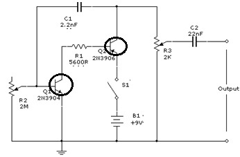
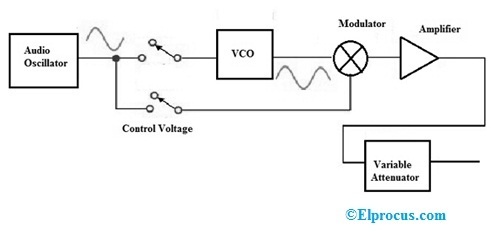
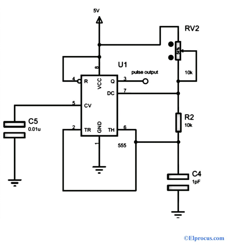
Signal Generator Circuit Working Types And Its Applications
Set the variable attenuator at minimum position.
. This whole setup with few alternations is able to. Connect the components and equipments as shown. It consists of following components.
Among the Microwave measurement devices a setup of Microwave bench which consists of Microwave devices has a prominent place. The Nvis 9000 series of Microwave Test Benches are precision made microwave systems which use standard type rectangular wave-guide components to illustrate the essential elements of. Gunn Power Supply.
-Gunn diode oscillator normally consist of a resonant cavity an arrangement for coupling diode to the cavity a circuit for biasing the diode and a. A microwave bench set up in real-time application would ORRN DV IROORZV í Microwave Bench Now let us take a look at the important part of this microwave bench the slotted line. Gunn Microwave Test Bench block diagram with components.
Where z g is known wave impedance and z is unknown impedance. Download scientific diagram Block diagram of the experimental test bench setup for microwave magnetic resonance studies with optical spin lamp pumping of ⁸⁷Rb atoms in the. Keep the control knobs of power supply as detailed below.
Set up the microwave test bench as shown in block diagram. The figure-2 depicts Gunn microwave test bench. Though the forward and reverse wave parameters are observed here there will be.
ONOFF switch - OFF Gunn diode bias knob - fully anti. Download song Microwave Test Bench Explanation and Streaming Song Collections Microwave Test Bench Explanation Latest MP3 on MP3 AUTOS and enjoy video clip Microwave Test.
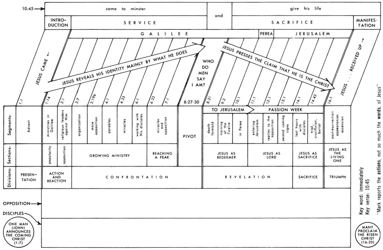
Mark 4 Commentary Precept Austin
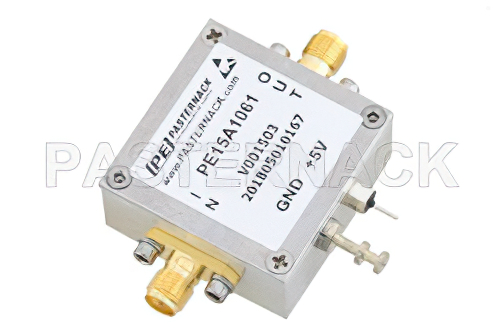
2 Db Nf Low Noise Amplifier Operating From 20 Mhz To 4 Ghz With 25 Db
40 Db Gain 25 Dbm Ip3 0 8 Db Nf 11 Dbm P1db 1 Ghz To 2
1 6 Db Nf Input Protected Low Noise Amplifier Operating From 30 Mhz To 1 5 Ghz With
Signal Generator Circuit Working Types And Its Applications
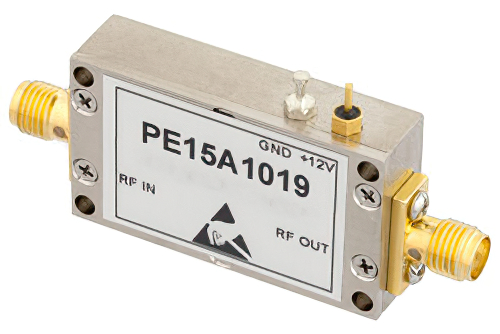
40 Db Gain 25 Dbm Ip3 0 8 Db Nf 11 Dbm P1db 1 Ghz To 2 Ghz Low Noise High Gain Amplifier Sma
High Spatial Resolution Distributed Strain Measurement In Optical Fiber With Rayleigh Scatter
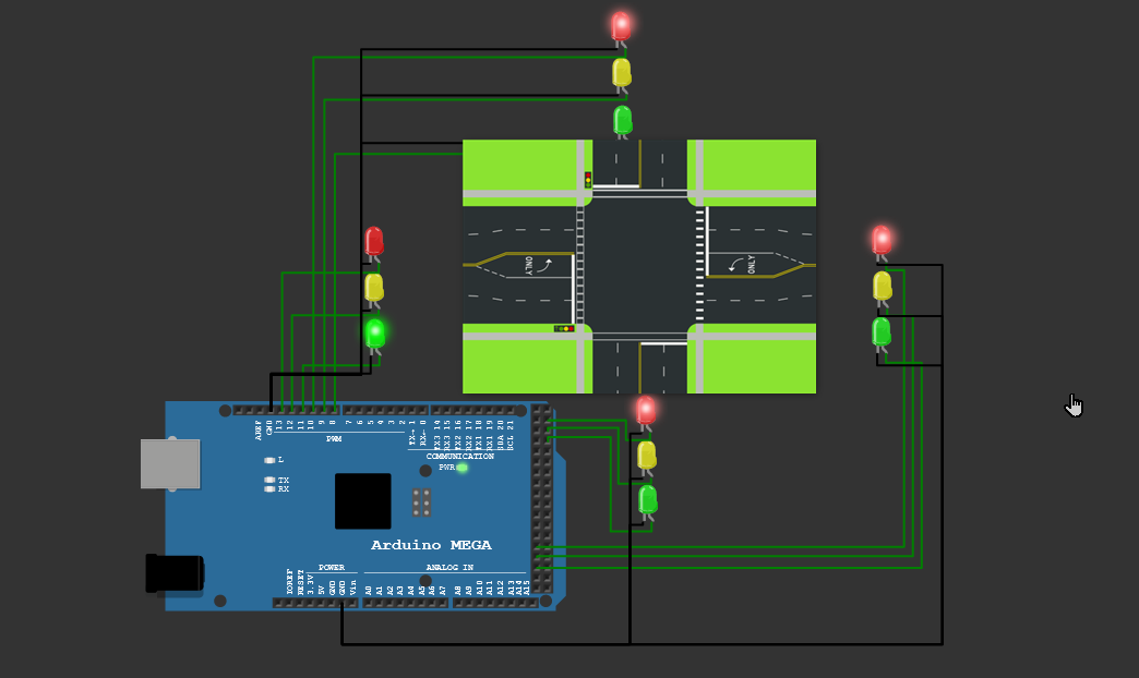
How To Rig Up The Given Schematic Diagram To Build A Traffic Light System Using Arduino Board With 3 Leds Red Yellow And Green That Represent Each Of The Traffic Lights Quora

Circuit Diagram For Diy Battery Welder Spot Welder Microwave Oven Transformer Youtube Spot Welder Welders Circuit Diagram
How To Rig Up The Given Schematic Diagram To Build A Traffic Light System Using Arduino Board With 3 Leds Red Yellow And Green That Represent Each Of The Traffic Lights Quora
How Does Agarose Gel Electrophoresis Work Quora
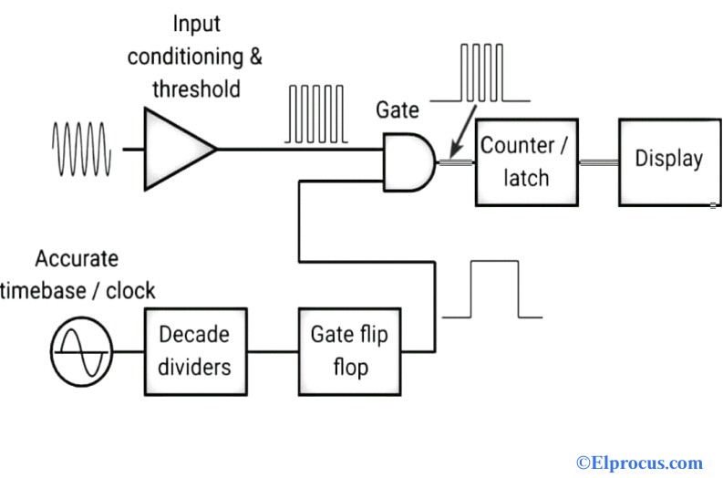
Frequency Counter Block Diagram Circuit Types And Its Applications
Sam S Laser Faq Laser Instruments And Applications
Frequency Counter Block Diagram Circuit Types And Its Applications

Schematic View Of The Ecr Ion Source Structure With Minimum B Magnet Download Scientific Diagram

Schematic View Of The Ecr Ion Source Structure With Minimum B Magnet Download Scientific Diagram
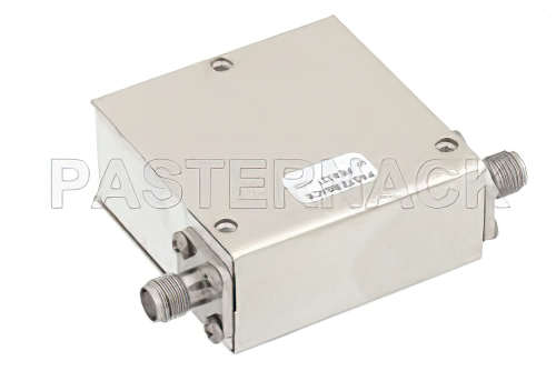
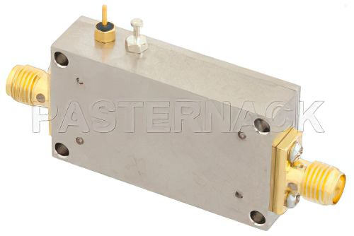
Isolator With 14 Db Isolation From 2 Ghz To 6 Ghz 25 Watts And Sma Female